The Western Electric Double Coil Coin Relay, 1911 to 1960
Published: 2/25/2024
Written By Dick Pitzer
COPYRIGHT November 9, 2012
Over 100 years ago, Mr. Oscar F. Forsberg, assignor to the Western Electric Company, filed a patent application for an Electromagnet on August 31, 1911; on November 17, 1914 the patent was issued (1,117,485). Today, this Electromagnet is commonly referred to as the Western Electric double coil relay.
On November 5, 1912, Mr. Forsberg, received a patent for a Coin Collector. Patent number 1,043,219 is referred today as the model 50A prepay coin collector and incorporates the double coil relay design. In summary, his invention consists of a coin gauge, coin chute or coin channel, a coin hopper, double coil relay, associated wiring, upper and lower housing, backplate and other related parts.
While the basic electrical and mechanical function of the Western Electric (W.E.) double coil relay remained unchanged from 1912 until the introduction of the single coil relay circa 1960, there were several manufacturing changes to the relay during the 50-year period. The purpose of this article is to point out those changes to give the reader a better understanding of which relay design and configuration used in various coin collectors (as-built at the factory) during these years. This article will show the differences in the relays beginning with those used in the model 50A of 1912 through the model 223G of the late 1950s. This will help the reader to identify which W.E. double coil relay he or she has in their collection and which coin collector it would have been installed in when built at the factory.
1912
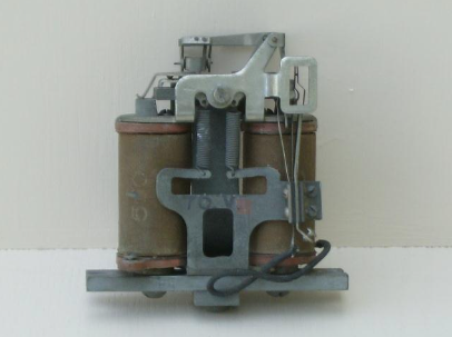
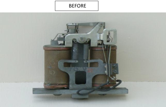
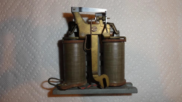
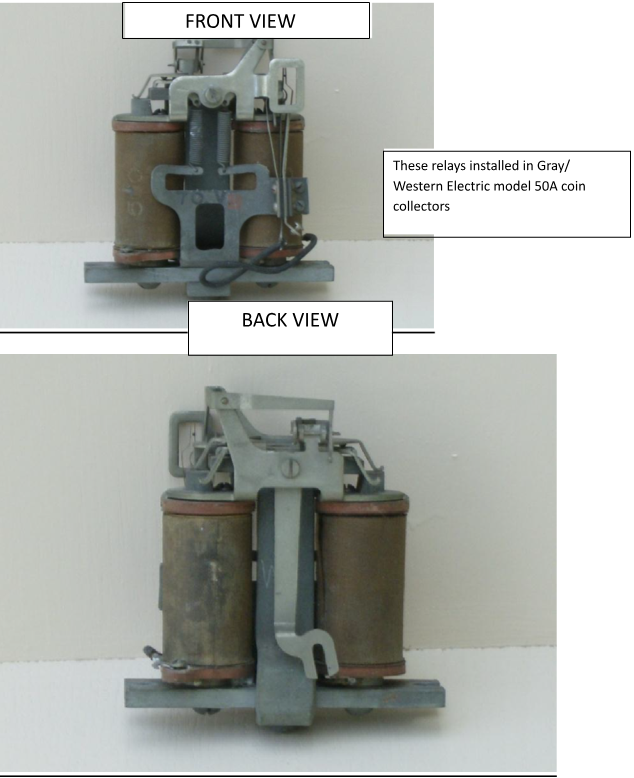
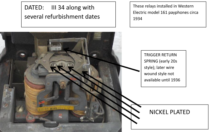
We’ll start with the prepay relay for the 50A coin collector built in 1912. This photo shows an early double coil relay and typical of that found in a 50A coin collector from 1912. The only exception is that the trigger return spring (see photo) was added in the early 1920s. This is an example where an update was added several years after the initial manufacture.
50A Prepay Double Coil Relay (1912)
The early double coil relays used two 500 ohm coils with a minimum operating voltage of +70. The upper operating limit of this relay is +110V. In the Coin Refund position a negative -110 volts is applied to the Tip side of the line with respect to Gnd. In the Coin Collect position a positive +110 volts is applied to the Tip side of the line with respect to ground. Several years later, the 500 ohm coils were replaced with 510 ohm coils with a minimum operating voltage of + 60 volts and an upper operating limit of + 110 volts (all voltage is direct current).
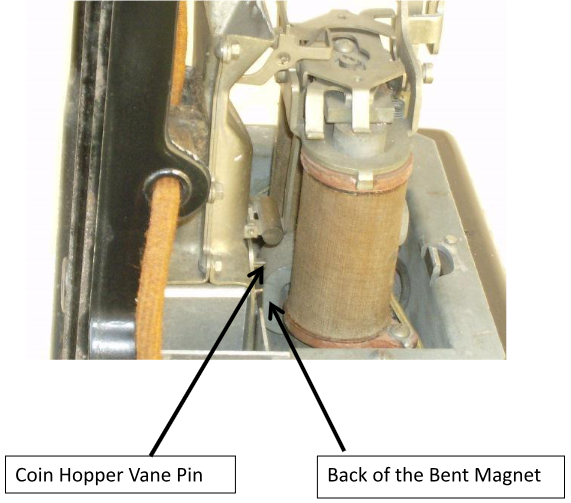
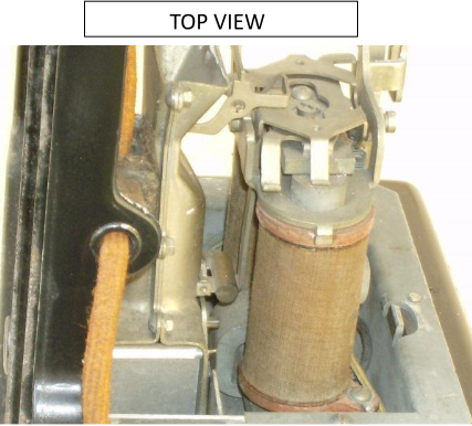
The early relay had a design flaw. As you see in the photo below, when installed, there is practically no distance between the Coin Hopper vane pin and the back of the permanent magnet, a.k.a the “Bent Magnet”.
Circa 1914
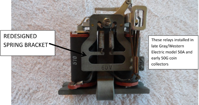
Spring Bracket Redesign
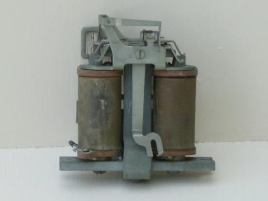
The early 1912 spring bracket, with the bent magnet installed toward the rear of the relay, was replaced with a redesigned spring bracket. As part of the redesign, the bent magnet was installed toward the front of the relay as shown in the AFTER picture below.
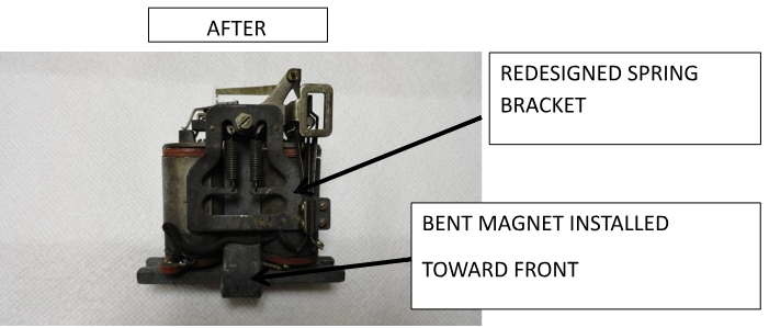
The new design eliminated the close tolerance between the coin hopper vane pin and the back of the bent magnet. The new spring bracket is shown, as early as 1914, installed on a similar W.E. electromagnet (relay) in a Substation Message-Register; patent number 1,162,007 filed Oct 15, 1914.
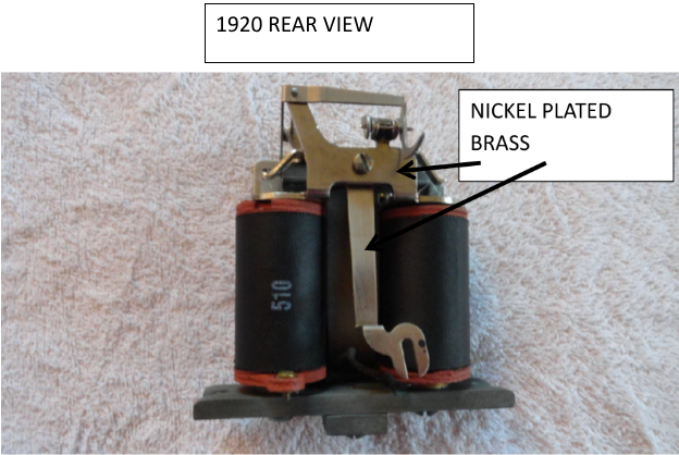
1920
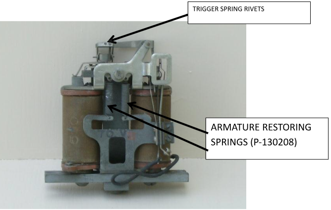
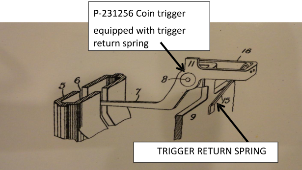
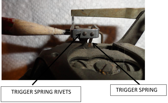
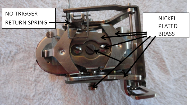
A coin trigger return spring was added in the early 1920s and serves as a shock absorber in order to eliminate the possiblility of false operation due to jarring according to the patent (1,545,662) filed on October 29, 1920. The trigger return spring is made of phosphor bronze. The photos below shows the patent drawing and a photo of an actual trigger return spring installed on one of my relays.
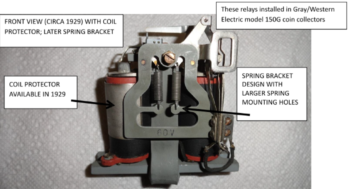
Circa 1929
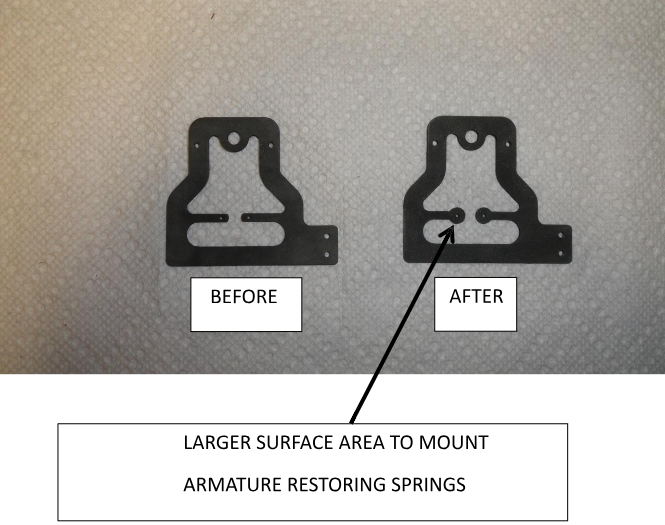
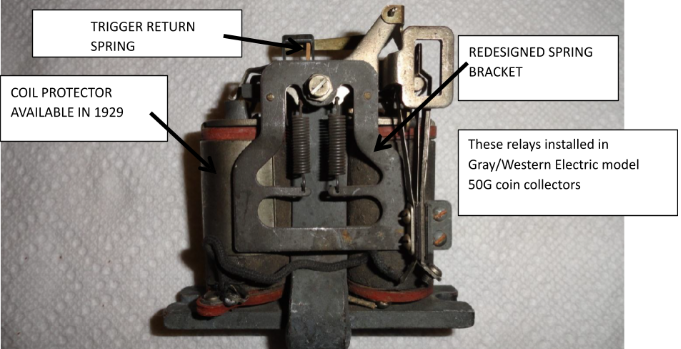
Sometime prior to 1929, Western Electric changed the spring bracket design again. A change was made to the spring bracket arms. The redesign offered a larger surface area for installing the armature restoring springs.
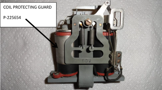
Protecting Guard for Coin Collector Relay Coil
In 1929, W.E. announced the development of a protecting guard (P-225654) for the left relay coil of No. 50 type coin collectors to protect the coil against damage in assembling the upper housing to the coin collector due to the corner of the housing in contact with the coil. The guard is made of nickel plated spring brass and slips around the left coil of the relay. It covers approximately three-quarters of the length of the coil and about two thirds of the circumference. The guard is snapped on the coil and held there under its own tension and a bent lug at the upper edge engages the slot in the spool head and prevents it from turning. The guard is shown below.
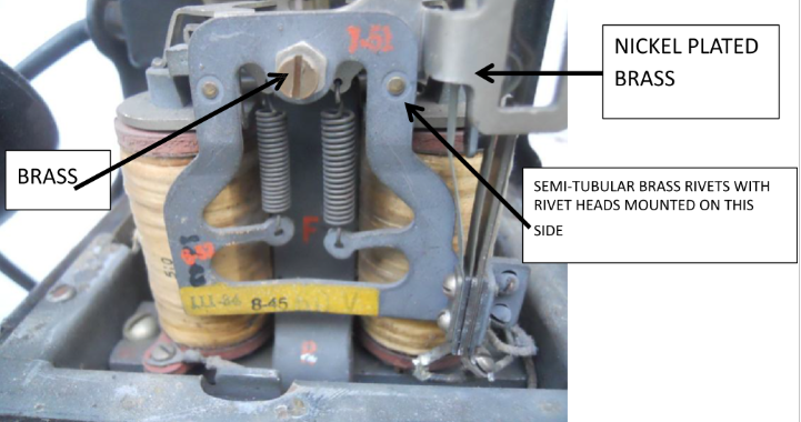
Circa 1934
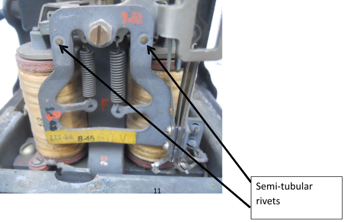
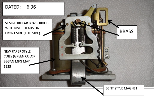
The 1912, 1921 and 1929 spring brackets, previously held to the armature pivot frame by two solid brass rivets, were replaced by semi-tubular brass rivets. The semi- tubular rivets are installed in reverse direction from the solid rivets. Specifically, the semi-tubular rivet heads are visible on the front of the spring bracket whereas the solid rivets are mounted in reverse direction (the heads are not visible from the front). The relay below is dated III 34 and shows the semi-tubular rivets. This style of relay would have been used on the W.E. 161 payphones in 1934.
New coil design
In May 1935 W.E. began the manufacture of a new paper filled, green colored, coin collector coil. The saving was estimated to be $0.20 per collector. These coils were for use in both the 7-J coin collector as well as public station coin collectors. The coil protecting guard (P-225654) was not used with the new coils. The older black cloth coils were stamped 510 to represent 510 ohm resistance; however, the new coils are not stamped even though they too are 510 ohm.
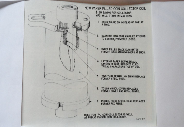
These new coils would have been used in the W.E. 161 payphone relays after May 1935.
1936
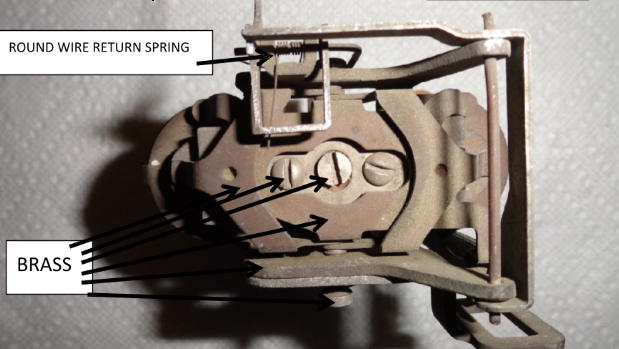
The trigger return spring of the early 1920s was replaced with a round wire return spring (P248496).
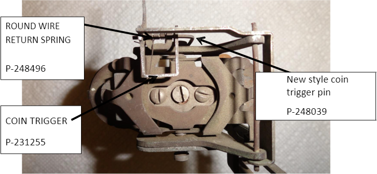
This style relay would be found on a W.E. 161 payphone.
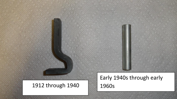
PERMANENT MAGNETS
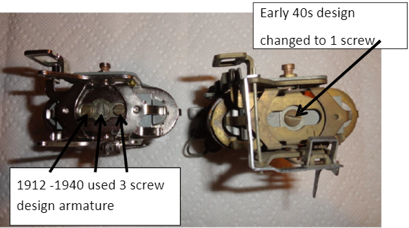
The two styles of permanent magnets are shown below. The first style (referred to as a bent magnet) was used from 1912 through 1940. The second style (round magnet) is found in relays beginning in the early 1940s. One problem with the bent magnets was a tendency to lose magnetism over time. These magnets had to be “recharged” from time to time.
1942-1948
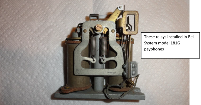
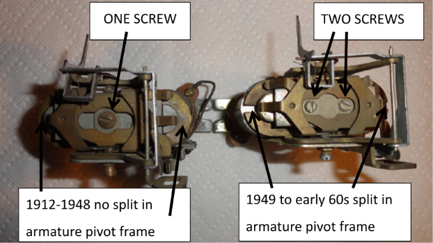
More changes by 1942. The previous armature with three screws on top (2 hold down and 1 center adjustment screw) was replaced with one screw. The photos below illustrate the change. In addition, the bent magnet was replaced with the round magnet. These relays were used in the 181G payphones.
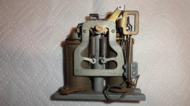
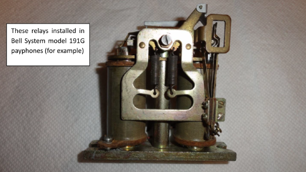
1949-early 60s
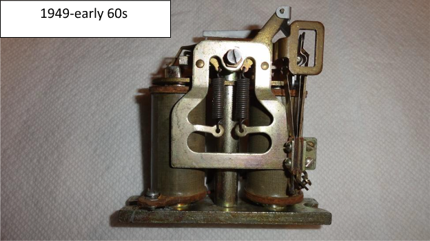
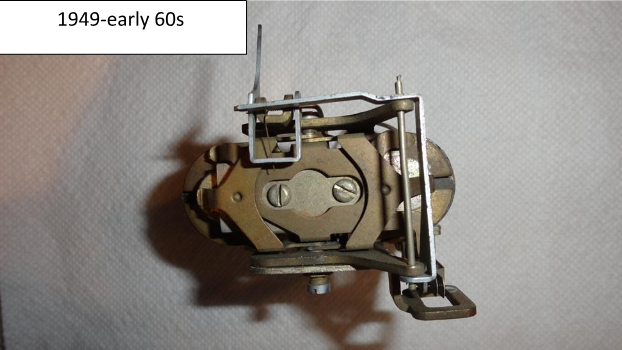
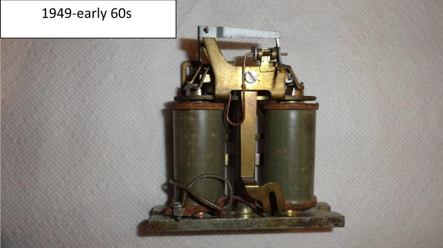
The pictures below show the style of relay found in Bell System model 191G payphones, for example.
There are slight differences from the 1942 relay. First the single screw on top of the armature was replaced with two screws (not adjustable). Secondly, the armature pivot frame is split where the upper part of the coil mates with the frame. This is discussed later with photos.
QUICK REFERENCE
1912-1920
Circa 1920 (with redesigned spring bracket; no return trigger spring)
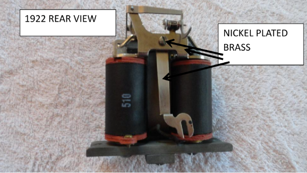
Circa 1922 with trigger return spring and redesigned spring bracket
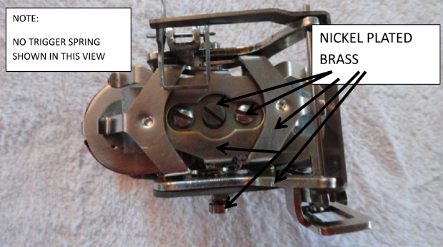
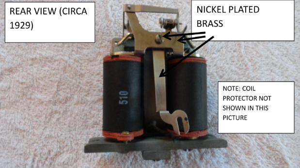
Circa 1929 front view
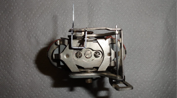
1929 top view
1936 Top View
1936 Rear View
ARMATURE REDESIGN (early 1940s)
The armature design was changed from 3 screws to 1 screw as shown below,
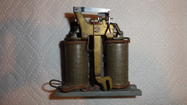
Early 1940s-1948 front view
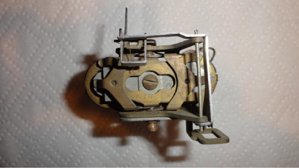
Early 1940s-1948 top view
Early 1940s-1948 rear view
1949 Armature pivot frame redesign & Armature
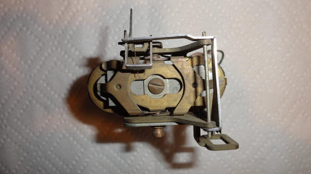
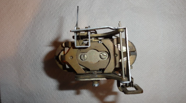
1949 to early 60s front view
1949 to early 60s top view
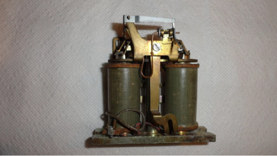
1949 to early 60s rear view
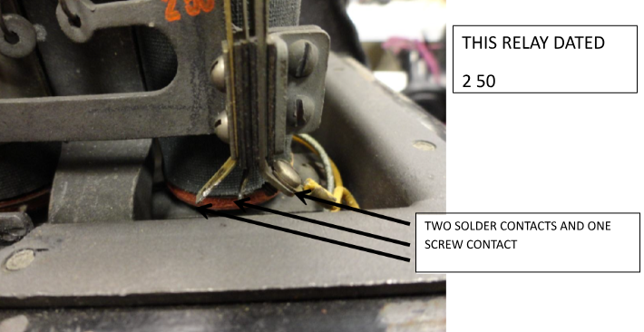
Two contact spring assembly P-145641 used on P-145749 model relays (1912-early 60s)
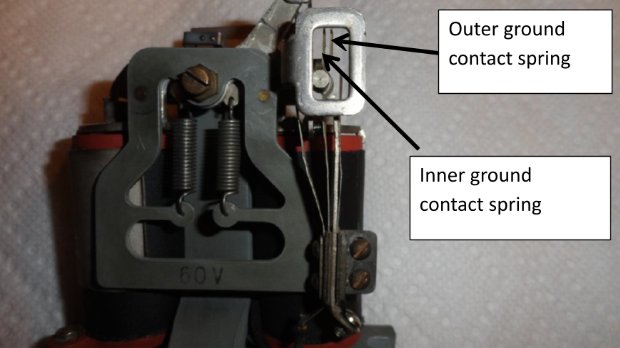
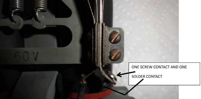
Three contact spring assembly PP-36410 used on P-145749 relays for the Gray No. 76 and the Gray/Western 50S; both Canadian
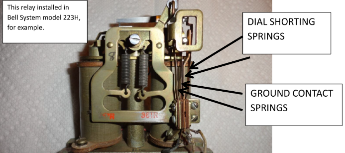
Shown in George Long’s patent 1,383,472 (filed May 1920 and issued July 1921) for an Automatic Electric Pay Station, the telephone is normally inoperative, the transmitter and dial being shunted by a circuit which passes through an additional pair of contacts in the relay spring assembly. When the coin trigger lever falls it causes these contacts to become separated, thus removing the shunt and placing the dial and transmitter in the telephone circuit.
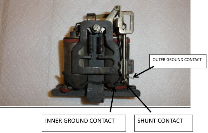
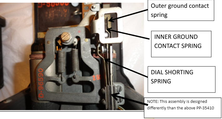
D-96590 Dial Shorting Relay, 3-Spring contacts
P-10C117 Dial Shorting Relay, 4-Spring contacts (late 50s early 60s)
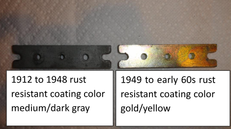
Relay mounting plate
The relay mounting plate rust resistant coating (gray) color (1912 to 1948) changed circa 1949 to a gold/yellow color.
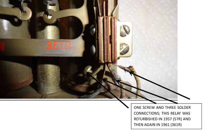
AS-BUILT versus REFURBISHED RELAYS
This article identifies relays in their as-built configuration (factory built) for various years from 1912 through the early 1960s. Some relays were sent back for refurbishment over the years for repair, adjustment, updating etc. Therefore, your relay may not reflect the factory as-built configuration.
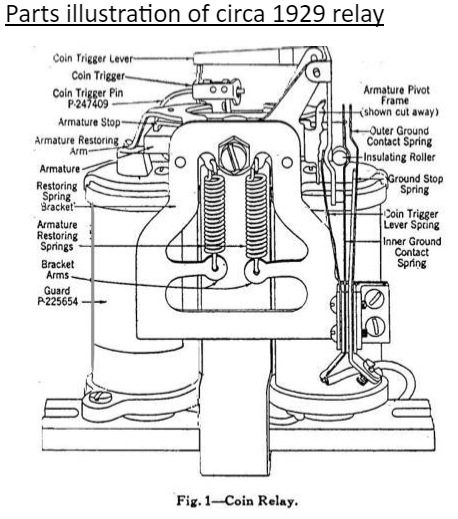
Parts illustration of circa 1929 relay
RECOMMENDED READING
I highly recommend you read Mr. Stan Schreier’s article titled, “Understanding the Western Electric Double Coin Relay” at:
http://www.antiquetelephonehistory.com/coinrelay.php
Mr. Schreier provides a detailed, easy-to-understand, explanation regarding the operation of the double coil relay. A fantastic article and a must read for those interested in just how the relay actually works!
MY THANKS to the following people in providing valuable information used in this article:
- Mr. Mike Davis
- Mr. Ron Knappen and his Payphone History Book
- Mr. Jim Engle
- Mr. Tom Adams
- Mr. Bob Bartlett